Arduino 102 for intermediatesRGB LEDThis project requires Arduino board, RGB LED (common cathode), 200 ohm or equivalent resistors, breadboard, and a USB-B cable.

RGB LED
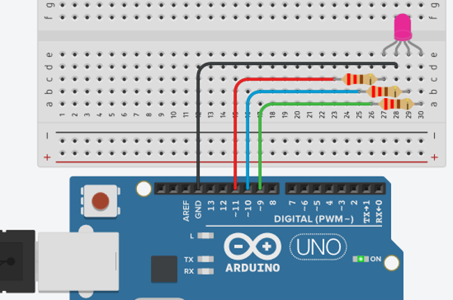
You can use the RGB(Red-Green-Blue) lights to add more functionalities to your project. You can also obtain additional colors like Magenta, Cyan, Yellow, and White by combining the basic RGB colors. The basic RGB led is available in two configurations, common anode and common cathode. In this tutorial, we will use the common cathode RGB. -In a common cathode configuration, the longest leg is cathode and it will be connected to ground. -Red, green, and blue legs of the RGB LED will be connected to PWM pins. In our example, we will use pin 11, 10, and 9 of the Arduino UNO.
Write your first Arduino code
Arduino RGB Circuit Simulation (TinkerCAD)
Seven Segment Display
There are two types of seven segment display, common anode (+) and common cathode (-).
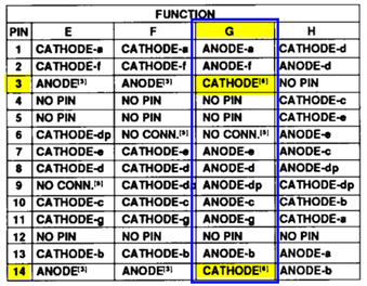
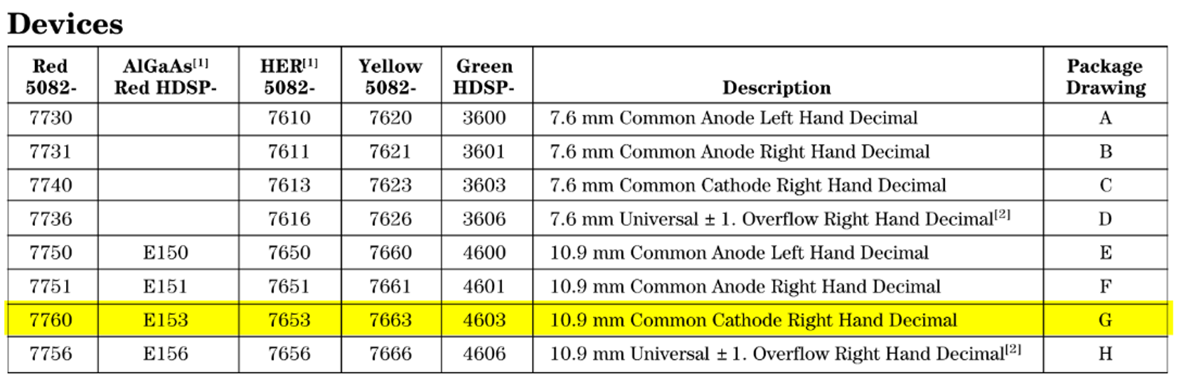
Common Anode Displays In this configuration, all the anode (+) legs are connected to Vcc, and individual segments are turned on and off by controlling the cathodes. In common Anode the Cathode(-) side of led’s are connected to a,b,c,d,e,f,g pins of seven segment display. To drive a given segment of a common anode display, current must be taken out of the corresponding segment’s terminal (sink). Common Cathode Displays In this configuration, all the cathode (-) legs are connected to Vcc or Arduino GPIO, and individual segments are turned on and off by controlling the the anodes. In common cathode displays, all of the cathodes are connected to ground and individual segments are turned on and off by switching power to the anodes. To drive a given segment of the common cathode display, current must be provided into the corresponding segment’s terminal (source). Seven Segment Display HP 5082-7760 Package Drawing - G
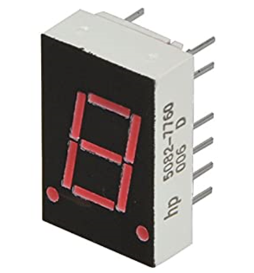
For this project, we will be using the HP 5082-7760 seven segment display (common cathode).
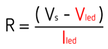
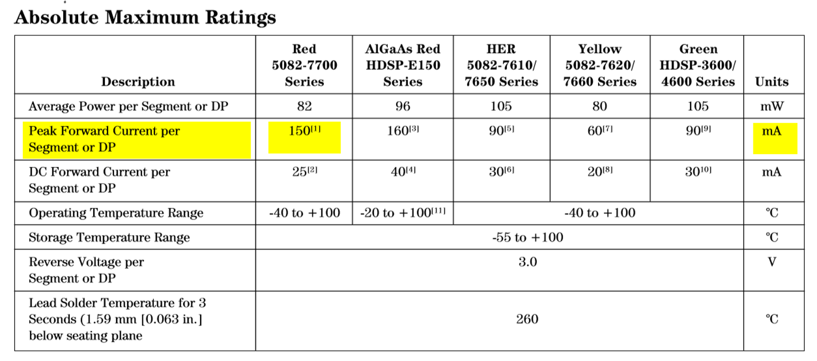
Most seven segment displays like the HP 5082-7760 series, they may work without current limiting resistors; however, it’s always recommended to use the appropriate resistor based on the datasheet. Typically for a standard red 7-segment display, each LED segment can draw about 15 mA. Using the Ohms law, R = V/I and values from the datasheet, we can determine the resistor value.
Determining LED resistor value
Our seven-segment display will need resistors at each leg to prevent the LED's from drawing to much current. Our datasheet tells us each LED has a maximum forward voltage of 150mA, so we use a little less to save the LED a bit, we're picking 125mA. Using Ohms Law we can easily determine the resistance needed.
From this calculation we can see that the seven-segment display requires very low resistor value of 22.67 ohm.
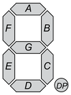
We need to put resistors at each anode pins of the seven-segment display. In our case, we can use a 22-ohm resistors or because the resistance value is too small, we can omit these resistors. Some online tutorials show using only one resistor at the cathode pin; however, this is not a recommended practice as the LED's would get different amounts of current for every digit you're trying to display. If you would only display the same digit every time, you can get away by calculating the total current resistor value but because each LED in our case is individually addressable; therefore, we need to put a resistor at all the anode pins or omit the resistors if the calculated resistance is too low. HP 5082-7760 7 Segment Display Pinout Now let’s go over the segment configuration so we know which pins light up which segments. The pinout for the 7-segment display is as follows.
Display control
In order to turn a specific segment, 5V will be supplied to the desired segment (A,B,C,D,E,F, or G). To get a digital number readout, the particular set of LEDs will be turned ON. For instance, to display the numerical digit 0, we will need to light up six of the LED segments (A,B,C,D,E,and F). Similarly, all the digits from ‘0 through 9’ and hexadecimal characters from ‘A through F’ can be displayed using a 7-segment display. 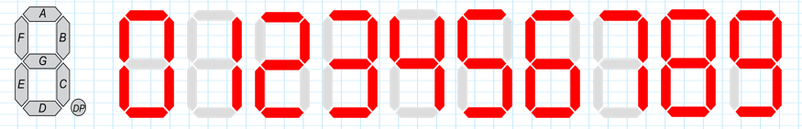
Circuit Connection and Simulation
Arduino Seven Segment Display Circuit Simulation (TinkerCAD)
Connect the circuit as shown above. Open Arduino IDE and select "File"-> "New" and create a new project file. Copy the following Arduino code into the newly created project, debug it and upload it to your Arduino board.
Have fun.... /*
SevenSegment
*/
#define DP 5 // PIN5
#define seg_A 6 // PIN6
#define seg_B 7 // PIN7
#define seg_C 8 // PIN8
#define seg_D 9 // PIN9
#define seg_E 10 // PIN10
#define seg_F 12 // PIN11
#define seg_G 11 // PIN12
int COUNT = 1; // counter
void setup()
{
for (int i = 5; i < 13; i++)
{
pinMode(i, OUTPUT); // Set PINs 5-12 as outputs
}
}
void loop()
{
// digitalWrite(DP, HIGH);
switch (COUNT)
{
case 1:
one ();
break;
case 2:
two ();
break;
case 3:
three ();
break;
case 4:
four ();
break;
case 5:
five ();
break;
case 6:
six ();
break;
case 7:
seven ();
break;
case 8:
eight ();
break;
case 9:
nine ();
break;
case 10:
zero ();
break;
case 11:
dot ();
break;
}
if (COUNT < 12)
{
COUNT++;
delay(1000);
}
if (COUNT == 12)
{
COUNT = 0;
delay(1000);
}
}
void zero ()
{
digitalWrite(seg_A, HIGH);
digitalWrite(seg_B, HIGH);
digitalWrite(seg_C, HIGH);
digitalWrite(seg_D, HIGH);
digitalWrite(seg_E, HIGH);
digitalWrite(seg_F, HIGH);
digitalWrite(seg_G, LOW);
digitalWrite(DP, LOW);
}
void one ()
{
digitalWrite(seg_A, LOW);
digitalWrite(seg_B, HIGH);
digitalWrite(seg_C, HIGH);
digitalWrite(seg_D, LOW);
digitalWrite(seg_E, LOW);
digitalWrite(seg_F, LOW);
digitalWrite(seg_G, LOW);
digitalWrite(DP, LOW);
}
void two ()
{
digitalWrite(seg_A, HIGH);
digitalWrite(seg_B, HIGH);
digitalWrite(seg_C, LOW);
digitalWrite(seg_D, HIGH);
digitalWrite(seg_E, HIGH);
digitalWrite(seg_F, LOW);
digitalWrite(seg_G, HIGH);
digitalWrite(DP, LOW);
}
void three ()
{
digitalWrite(seg_A, HIGH);
digitalWrite(seg_B, HIGH);
digitalWrite(seg_C, HIGH);
digitalWrite(seg_D, HIGH);
digitalWrite(seg_E, LOW);
digitalWrite(seg_F, LOW);
digitalWrite(seg_G, HIGH);
digitalWrite(DP, LOW);
}
void four ()
{
digitalWrite(seg_A, LOW);
digitalWrite(seg_B, HIGH);
digitalWrite(seg_C, HIGH);
digitalWrite(seg_D, LOW);
digitalWrite(seg_E, LOW);
digitalWrite(seg_F, HIGH);
digitalWrite(seg_G, HIGH);
digitalWrite(DP, LOW);
}
void five ()
{
digitalWrite(seg_A, HIGH);
digitalWrite(seg_B, LOW);
digitalWrite(seg_C, HIGH);
digitalWrite(seg_D, HIGH);
digitalWrite(seg_E, LOW);
digitalWrite(seg_F, HIGH);
digitalWrite(seg_G, HIGH);
digitalWrite(DP, LOW);
}
void six ()
{
digitalWrite(seg_A, HIGH);
digitalWrite(seg_B, LOW);
digitalWrite(seg_C, HIGH);
digitalWrite(seg_D, HIGH);
digitalWrite(seg_E, HIGH);
digitalWrite(seg_F, HIGH);
digitalWrite(seg_G, HIGH);
digitalWrite(DP, LOW);
}
void seven ()
{
digitalWrite(seg_A, HIGH);
digitalWrite(seg_B, HIGH);
digitalWrite(seg_C, HIGH);
digitalWrite(seg_D, LOW);
digitalWrite(seg_E, LOW);
digitalWrite(seg_F, LOW);
digitalWrite(seg_G, LOW);
digitalWrite(DP, LOW);
}
void eight ()
{
digitalWrite(seg_A, HIGH);
digitalWrite(seg_B, HIGH);
digitalWrite(seg_C, HIGH);
digitalWrite(seg_D, HIGH);
digitalWrite(seg_E, HIGH);
digitalWrite(seg_F, HIGH);
digitalWrite(seg_G, HIGH);
digitalWrite(DP, LOW);
}
void nine ()
{
digitalWrite(seg_A, HIGH);
digitalWrite(seg_B, HIGH);
digitalWrite(seg_C, HIGH);
digitalWrite(seg_D, HIGH);
digitalWrite(seg_E, LOW);
digitalWrite(seg_F, HIGH);
digitalWrite(seg_G, HIGH);
digitalWrite(DP, LOW);
}
void dot ()
{
digitalWrite(seg_A, LOW);
digitalWrite(seg_B, LOW);
digitalWrite(seg_C, LOW);
digitalWrite(seg_D, LOW);
digitalWrite(seg_E, LOW);
digitalWrite(seg_F, LOW);
digitalWrite(seg_G, LOW);
digitalWrite(DP, HIGH);
}
If you have enjoyed the Arduino intermediates tutorial, then check out the topic Arduino 103 in this website for more advanced Arduino projects. »»» END of Arduino 102 »»» |
|