BREADBOARD POWER SUPPLY (BBPS):
Disclaimer: In this DIY project, we will design, assemble, and test a breadboard power supply that can provide regulated and selectable DC voltage.
Design procedures:
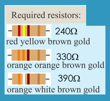
First, select a voltage regulator based on the design requirements. For this project, we will use the LM317 voltage regulator and the design is based on the Texas Instruments application note and datasheet of the LM317-N. A voltage regulator is a constant voltage source that adjusts its internal resistance to any occurring changes of load resistance. It also provides a constant voltage at the regulator output. Below is the link to the datasheet of the voltage regulator: http://www.ti.com.cn/cn/lit/ds/symlink/lm117.pdf The LM317-N is an adjustable positive voltage regulator. It is capable of supplying in excess of 1.5A over a 1.25V to 37V output range. As per the datasheet, LM317 has the following design features:
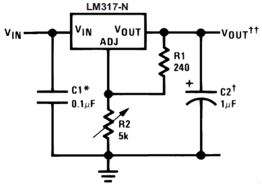
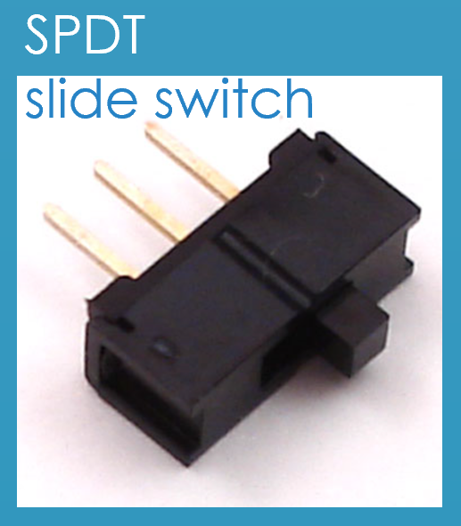
However, our design requires two voltage outputs, 5V and 3.3V instead of variable output voltages. Therefore, we need to modify the circuit in figure 2. Using the potentiometer or the variable resistor, R2, a variety of output voltages can be made possible. Similarly, we can create a voltage division circuit and a switch to replace the variable resistor functions in the above example.
Regulated section:
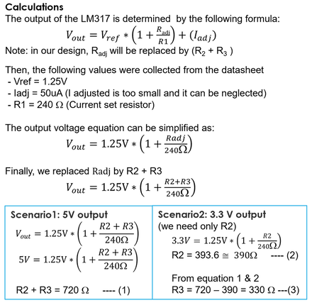
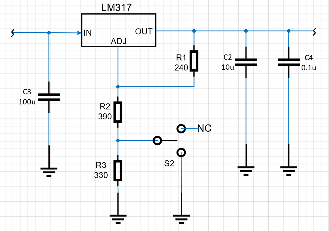
Based on the calculation, we need 330 and 390 ohm resistors for the voltage division and 240 ohm for the current limiter resistor, R2. Next, using the recommended values from the datasheet, the following capacitors were selected as shown in figure 3. - Filter capacitor, C1 = 100uF to filter-out input transient - Output capacitor, C2 = 10uF to improve output impedance - Bypass capacitor, C3 = 0.1uF to prevent ripple from being amplified. •R1: current set resistor •R2 and R3: voltage division to get different output voltages. Finally, a voltage selector switch is added to the circuit and finalized the design of the regulated section.
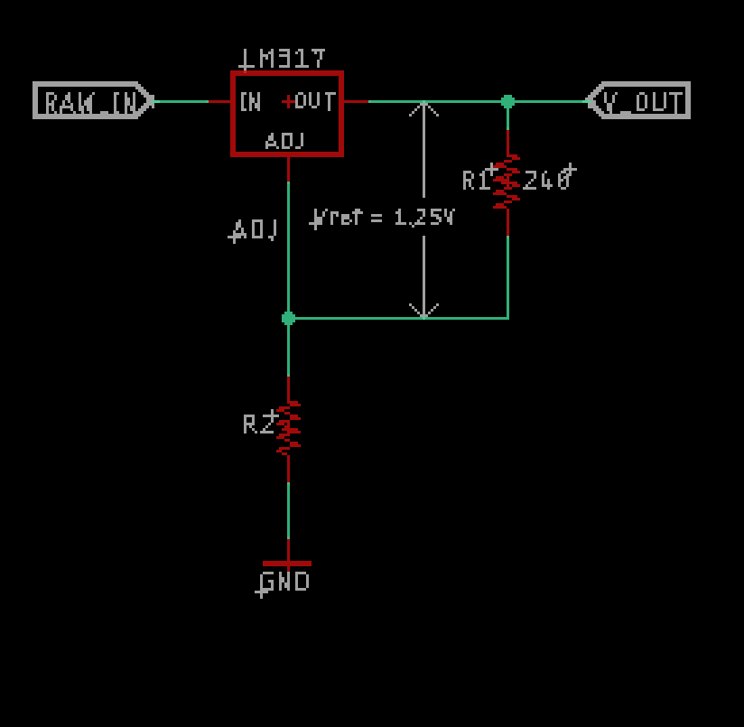
LM317 Voltage CalculatorThe LM317 needs two external resistors R1 and R2 to adjust the output voltage as shown in the voltage division schematics. The output voltage depends on the values of R1 and R2. Enter these values into the calculator to calculate the output voltage.
Unregulated section:
The unregulated section of the BBPS design added protection devices, switch and DC inputs devices. •DC Barrel Connector (primary input) •Header Pins terminals (secondary input) •On/Off Switch •Reverse Protection Diode •PTC resettable Fuse (500mA) for overcurrent protection. (PTC is a positive temperature coefficient) The circuit diagram for the unregulated section of the BBPS is sown in figure 4. 
Figure 4. Unregulated section of the BBPS
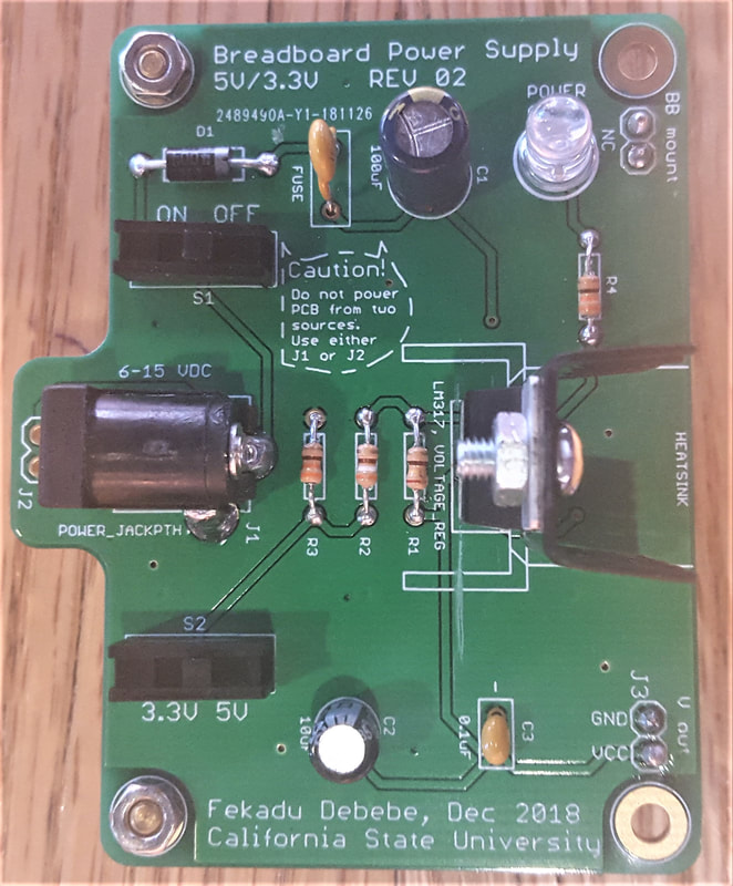
Final Design:
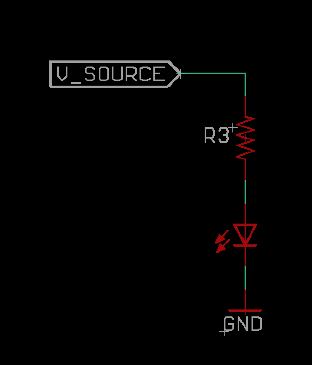
Finally, the regulated and unregulated section of the design are combined. Then, an LED with a series resistor, 330 ohm was added for power on indication and the circuit design phase was completed as shown in figure 5 below. 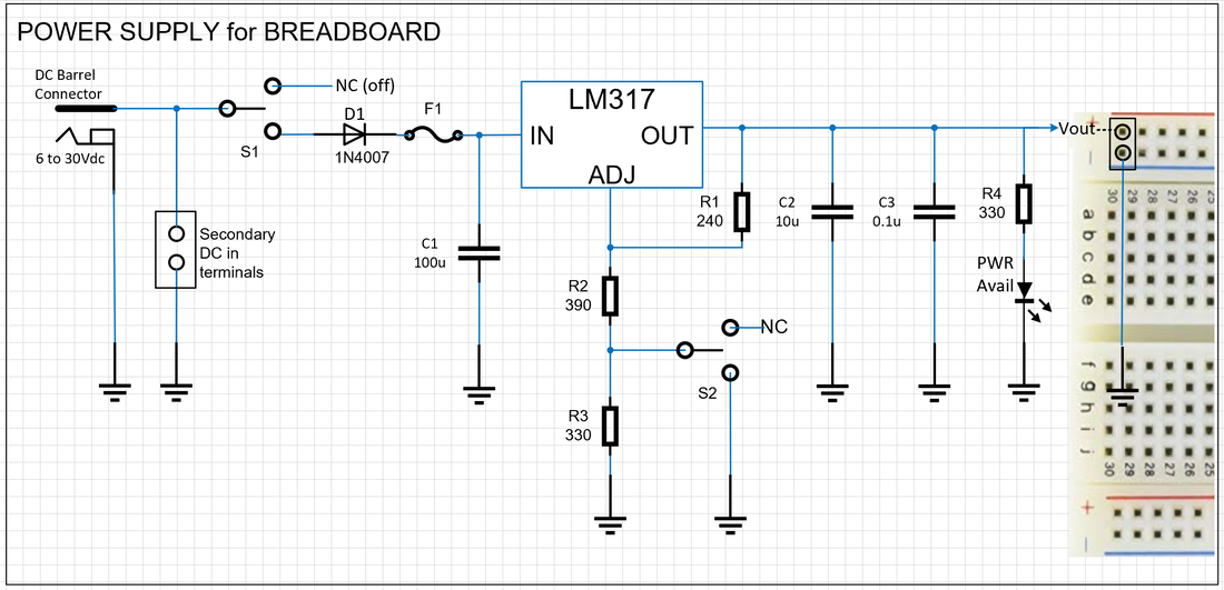
Figure 5. Breadboard power supply (5V/3.3V)
To find the appropriate resistor value, you can use the formula: R = (Vs - Vf) / If
The LED Resistor Calculator can also be used to calculate the resistance required to drive the LEDs from a voltage source at a specified current level.
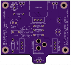
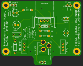
PCB Design:
The PCB Design of this project is done in Eagle CAD 9.2.2 student version. The program is free for students and it can be obtained from Autodesk website. Before starting the PCB layout, there is one important note in the application note of the LM317, "if the current set resistor is placed too far from the output terminal, then the increased trace resistance will cause an error voltage drop in the adjustment loop and it will reduce the load regulation performance." Therefore, the current set resistor, R1 (240 ohm) in our case, must be placed as close as possible to the output terminal of the regulator to minimize trace resistance and maximize load regulation performance. Considering this information and the design requirements, the PCB was designed in Eagle-CAD program as shown in figure 6 below. 
Figure 6. Eagle CAD PCB layout of the BBPS.
(Some layers are turned off for clarity)
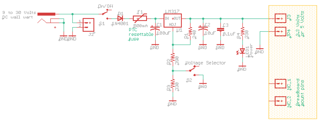
Figure 7. Eagle CAD schematics of the BBPS
After the PCB layout is completed, run both ERC (for electrical rule check) and DRC (for design rule checking). Note: ignore the "unconnected pin NC_1 and NC_2" ERC errors or approve these errors during check. These two pins do not have electrical connections, they are there for breadboard mount only. DRC check should say "No errors"
Then, generate a zipped Gerber file and send it to a PCB manufacturing company like OSH park, JLCPCB, or PCBWAY. I have used these three companies before and they are doing a great job. If you need a quick turnaround time, then OSH Park is preferred as they are located here in USA. If you want to trade in quick turnaround time for a cheaper price, then JLCPCB is the cheapest. If you need more quantity (10 PCBS) for the same price, then PCBWAY is the go to place. But do your due diligence to compare at least four or five companies to meet your pocket and quality requirements. In my case, version 1 was manufactured by OSH Park and version 2 was manufactured by JLCPCB, both PCBS have great quality but different turnaround time and price.
Component assembly:
The following Tools are required to assemble the PCB : - Soldering Iron - Solder - Wire cutters - Multimeter (optional - for quick test after assembly) The following parts, (except item number 15,16, and 17) are required to assemble the PCB.
Application:
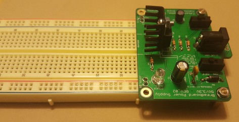
After all the components are assembled, double check the correct installation of all the components; especially, the polarity of capacitor C1 and C2. Then, it's time to plug it into the breadboard. Align the VCC and GND header pins with the power rails of the breadboard. The other two header pins will fit on the other side of the breadboard power rail. These two header pins are there for mounting purpose only and they don't have any electrical connection on the PCB. Then, connect any Wall Power Adapter from 6V to 15 V DC wall wart to the barrel jack. Next, turn on the On/Off switch and select either 3.3 or 5V via the switches. The LED should light on and the BPPS is ready for use.
Test:
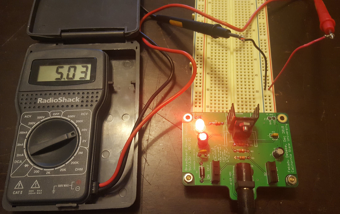
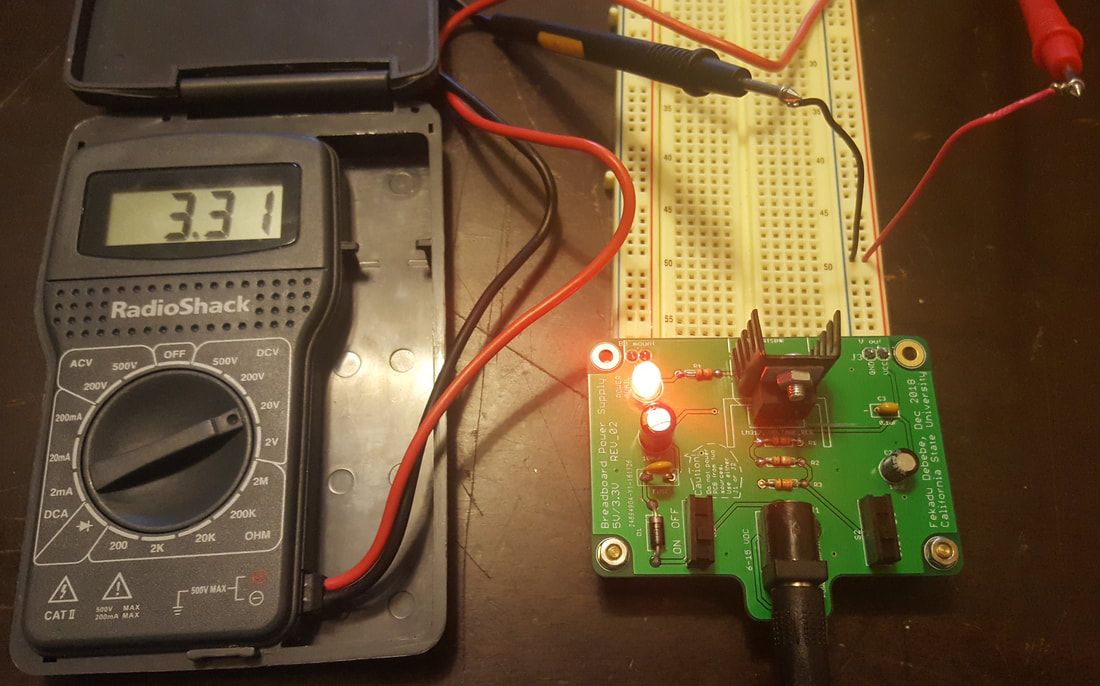
Now, we are ready to use the power supply but we have to test the voltage outputs of the BBPS. I my case, I have performed the output voltage test and both 3.3 and 5V outputs were successfully obtained from the BBPS as shown in the following figures.
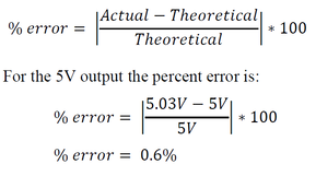
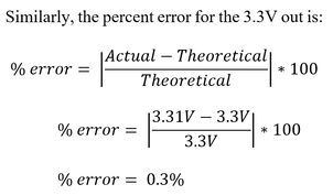
The percent error is calculated as follows:
>>> End of BBPS design >>>Have a question or comments?
- Click here to contact us |
|
|
|
|