DIGITAL LOGIC DESIGNDIGITAL LOGIC DESIGNBINARY COUNTER CIRCUIT
A counter is a device that increment or decrement the value of the counter by one count for clock signal. A binary counter can be constructed from JK-flip-flops by taking the output of one flip-flop to the clock input of the next flip-flop. However, a binary counter is also available in a single IC that is fully programmable to count in both “Up” and “Down” directions. In this project, we will use the 74LS193 Synchronous 4-Bit Binary Counter along with and a 555 timer and 7-segment decoder. The 74LS193 IC is a synchronous up/down 4-bit binary counter. Synchronous operation is provided by having all flip-flops clocked simultaneously. Data sheet for 74LS193 can be downloaded here: 74LS193 Datasheet
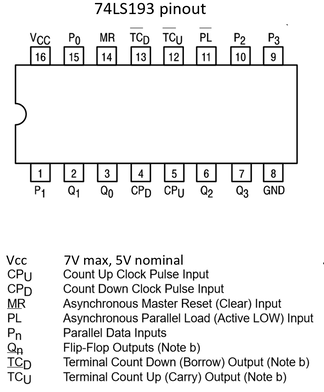
Pin-out for the 555 timer, 74LS193 up/down counter, and 74LS47 seven segment decoder.
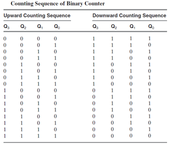
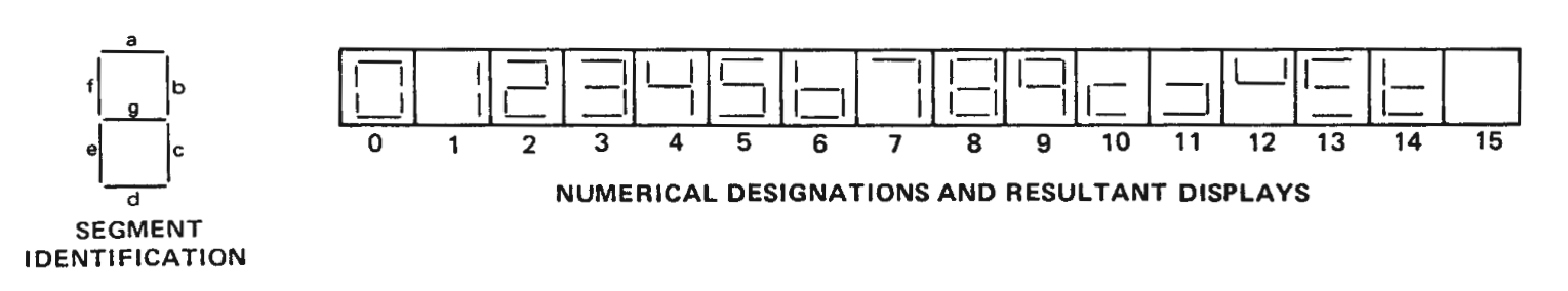
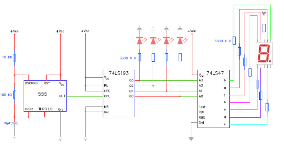
The schematic below shows the "UP" counting sequence of the binary counter circuit. The output is displayed on the four LEDs and on the seven segment display. The 4-bit Up/Down synchronous counter will have a maximum count of zero (0000) to fifteen (1111). Then the 4-Bit counter advances upward in sequence (0,1,2,3,4,5,6,7,8,9,10,11,12,13,14,15) and the binary output will be displayed on the LEDs and the decimal outputs (0,1,2,3,4,5,6,7,8,9) on the 7-segment display. The seven segment will display the digits from 0 to 9 only due to the nature of the BCD-TO-SEVEN-SEGMENT DECODER (74LS47) as shown in the figure below.
The following schematics is for Up/down counter (0 - 15) using 555 timer, 74193 counter, and 7447 decoder.
Binary Counter
To change the above breadboard circuit to DOWN counting, use the same logic:
- Connect the output from the 555 timer to the CPD of the 7493. - Connect the CPU to + Vcc. Breadboard setup in circuits.io
Before constructing the circuit onto the actual breadboard, it is recommended to use online simulators and verify the circuit can perform what it supposed to accomplish. The figure below shows the Up/down counter simulation in circuits.io program. The simulation program does not contain the model for the 74LS47 7-segment decoder IC but CD4511 can also be used along with the 555 timer and 7493 counter. 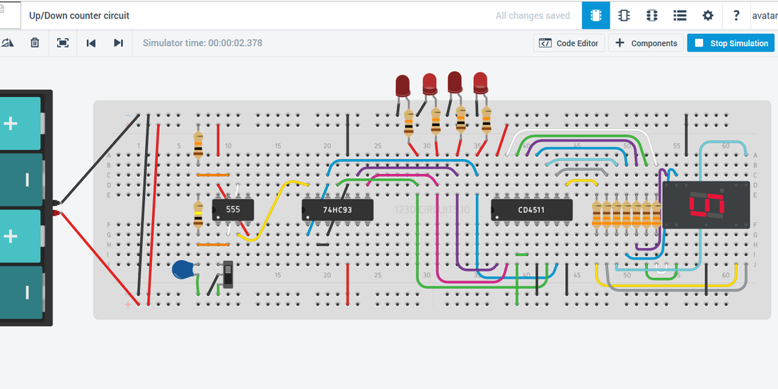
MODULO 6 counter (counting from 0 - 5 only)
MODULUS or MOD counter is a circuit that counts up to a pre-set modulo number before resetting the counting sequence. Now, let's modify the above up/down counter to get a MOD 6 counter. To construct a modulo 6 circuit, add a 7408 - AND gate IC and modify the above circuit as shown in the circuit diagram below.
- Tap from the Q0 and Q2 outputs and connect them to 7408 - AND gate input terminals. - connect the output from the AND gate to the MR terminal of 74193 counter. 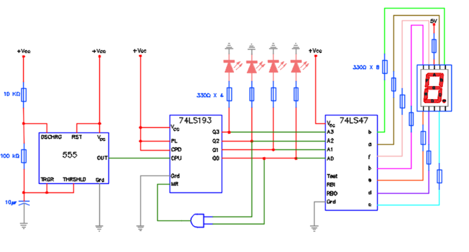
Binary Counter - MODULO 6 counter
FOUR BIT BINARY FULL ADDER
A four-bit full adder circuit with a carry is also available in different IC packages. For this project, we will use the 74LS83. To build a four bit binary adder/ subtractor circuit with mode selector, we need dip switches, one exclusive OR gate, one 7483 or similar IC, and LEDs. The 74LS83 IC adds two 4-bit binary words (A plus B) plus the incoming carry. The binary sum appears on the sum outputs (∑1–∑4) and outgoing carry (C4) outputs.
74LS83 datasheet 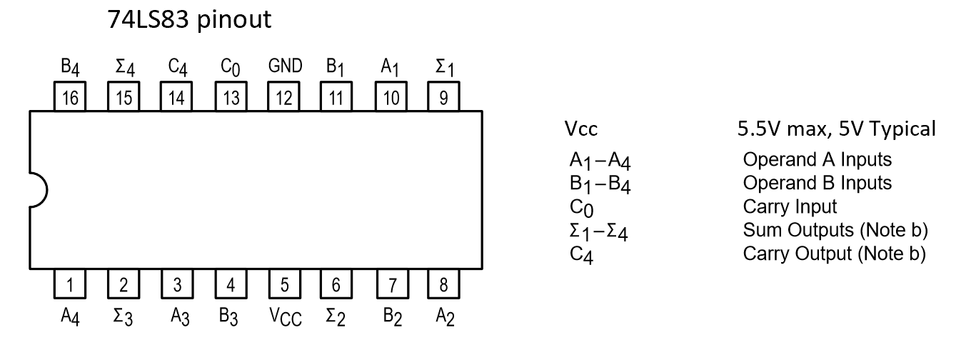
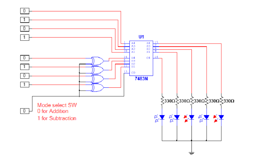
Below is the circuit diagram for a four-bit full adder. Once the circuit design is completed, we can use the mode selector switch to change the addition mode to a subtraction mode by flipping the "0" to a "1".
|
Basic Logic Gates
Flow Chart tooldraw.io is completely free online diagram editor built around Google Drive(TM), that enables you to create flowcharts, UML, entity relation, network diagrams, mockups and more.
Your data is stored only in Google Drive, so no additional third-party to trust with your data. draw.io can import from .vsdx, Gliffy(TM) and Lucidchart(TM) files. Circuit simulation tools1. Multisim by National Instruments Multisim is an electronic schematic capture and simulation program which is part of a suite of circuit design programs. It is one of the better-known tools on the market for both circuit design and simulation. The software allows users to design their own circuits and run simulations using a SPICE-based. 2. Autodesk Circuits Autodesk Circuits, aka tinkercad, has a virtual breadboarding and circuit design application. The Electronic Lab of the 123D Circuits app allows user to Simulate and program Arduino and breadboard components. Test your Arduino code in a real-time simulation environment and see your designs come to life in the browser. The best thing is it’s all free! 3. EveryCircuit If you are looking for a simulation app to simulate your circuit as you go, EveryCircuit is a good way to go. EveryCircuit is an interactive circuit simulation app that is provided to Android, iOS and Chrome users. EveryCircuit app is also free for students and teachers. 4. Circuitscloud.com Circuits Cloud is an online free analog/digital circuits simulator. It is a NGSPICE-based simulator. Circuits Cloud is a cloud-computing-based application, where the user can access the application through the internet, while all their data are stored online. 5. EasyEDA is a web-based EDA tool suite that enables hardware engineers to design, simulate, share - publicly and privately - and discuss schematics, simulations and printed circuit boards. |