VHDL - Programming the Field Programmable Gate Array (FPGA)Introduction to VHDLVHDL (VHSIC-HDL, Very High Speed Integrated Circuit - Hardware Description Language) is a hardware description language used to describe the behavior of digital circuit designs such as field-programmable gate arrays and integrated circuits. A digital system can be represented at different levels of abstraction.
The highest level of abstraction is the behavioral level of VHDL that describes a digital system in terms of how it behaves. A behavioral description specifies the relationship between the input and output signals instead of describing its components and interconnection between the components. The behavioral description could be a Boolean expression or a Register Transfer Level of abstraction. The structural level abstraction describes a system as a collection of gates and components. A structural description could be compared to a schematic of interconnected logic gates. It is a representation that is usually closer to the physical realization of a system. VHDL Constructs - Data Types In VHDL, every signals, variables, and constants must have a data type declaration. Some data types are synthesizable, while others are only for modeling purpose. User-defined types are created with type declarations. Predefined types can be divided into several categories: scalar, composite, access, and file. In addition, there are non-predefined types established by the IEEE standard 1164. Each of these types is listed below. 1. Scalar Types - Enumerated Data Type: An enumerated type is a data type in which the exact values are defined. - bit - "0 or 1" - boolean - "true or false" - character - "literals: 128 characters of the ASCII character set" - Severity_level (literals: note, warning, error, failure) - Numeric - Integer - Physical - Floating_point 2. Composite Types - Array - String (1-dimensional array of type character) - Bit_vector(1-dimensional array of type bit) - Record - Access Types (see access) - File Types (see file) 3. Non-predefined Types: In addition to the predefined types, IEEE standard 1164 adds the following types that are commonly used for modeling digital logic: - Std_ulogic (an enumerated type with the values 'U', 'X', '0', '1', 'Z', 'W', 'L', 'H', '-') - Std_logic (same as std_ulogic except that this is a resolved type) - Std_ulogic_vector (an array of std_ulogic) - Std_logic_vector (an array of std_logic) 4. Predefined-Types: Types defined by the IEEE standard 1076.3 are: - Unsigned (an array of std_logic) - Signed (an array of std_logic) - Overloaded arithmetic and conversion operators for types unsigned and signed are defined in the package numeric_std. More information on selecting a data type can be found in the Design Considerations section of the IEEE VHDL Reference Manual. VHDL Ports The inputs and outputs of a VHDL system are called ports. Each port needs to have its name, mode, and type specified at the entity level using port declarations and the keyword port. Port directions IN Input port OUT Output port INOUT Bidirectional port BUFFER Buffered outputs (can be read by the architecture of the entity) Model Constructs
1. Libraries and Packages A library can be considered as a place where the compiler stores information about a design project. VHDL libraries provide a set of packages, components, and functions that simplifies the design. The keyword "library" is used to shows that library packages are going to be added into the VHDL design file. Packages provide a collection of sub-libraries. For example "std_logic" is defined in the package ieee.std_logic_1164 in the ieee library. In order to use the std_logic, we needs to specify the library and package at the beginning of the VHDL file as follows: library IEEE; 2. Entity
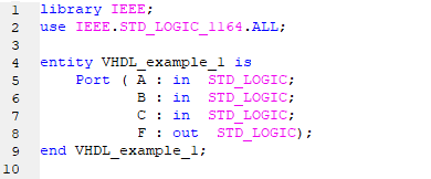
An entity is a specification of the design interfaces. The entity declaration in VHDL defines the name of the entity and lists the input and output ports. The mode describes the direction data is transferred through the port and can take on values of either in, out, inout, or buffer. The type is one of the legal data types described above. Port names with the same mode and type can be listed on the same line separated by commas. entity entity_name is
3. Signal Declarations
Signals represent wires within the system and they do not have a direction or mode. Signals that are used for internal connections within a system are declared inside the VHDL architecture. Signals cannot have the same name as a port in the system and each signal must be declared with a type. Syntax: signal name : <type>; Examples: - signal A : bit; - signal x, y, z : integer; - signal F : bit_vector (15 downto 0); - signal C_int : integer range 0 to 255; 4. Architectures
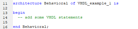
The architecture in VHDL describes the behavior of a system. It is a specification of the design's internal implementation. The architecture is where the majority of the design work is conducted. Besides, a single entity can have multiple architectures.
|
|