Arduino 101 for beginnersIntroduction to Arduino
Arduino is an open-source microcontroller and software IDE ( Integrated Development Environment) that is literally changing the world.
Why Arduino?
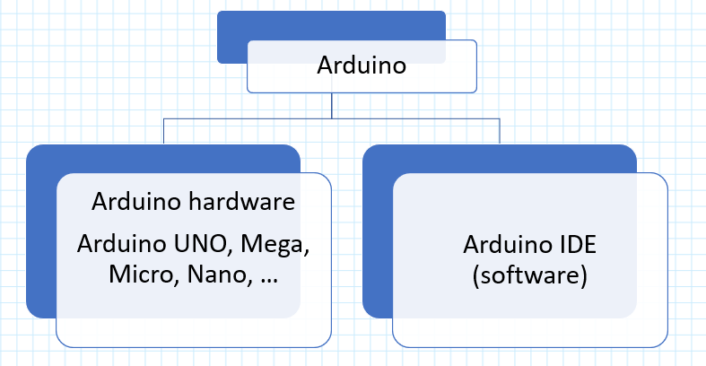
Arduino is: •Open-source software – Arduino IDE (free) •Inexpensive and Open-source hardware – If you have circuit design experience, you can clone and manufacture your own Arduino board. •Easy-to-use for beginners •Easy to write and debug the code •It works with Mac and Windows Arduino Hardware
Arduino boards are easy to use and ready to power your first creative projects. * Note: It is recommended to use the authentic Arduino board instead of the counterfeit boards that says, ‘Arduino compatible’. By buying the original Arduino we can help the open-source community. Entry level Arduino boards The following boards are the best to start learning the basics of electronics and coding. For enhanced features and Internet of things capable boards, refer to Ardunio website. 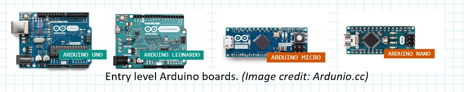
Arduino Board Comparison |Widely Used Arduino'sArduino - UNO
The Arduino UNO is the best board to get started with electronics and coding. If this is your first experience tinkering with the platform, the UNO is the most robust board you can start playing with. The UNO is the most used and documented board of the whole Arduino family.
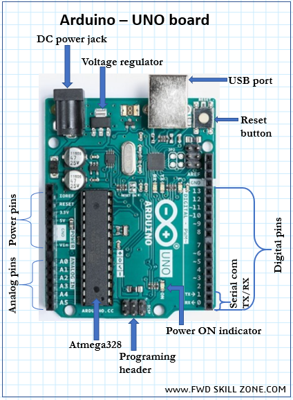
Arduino – UNO - Pinouts
The Arduino UNO pinout diagram given here is an entry level introduction only. Expert level users can refer to the Arduino website for detail information.. 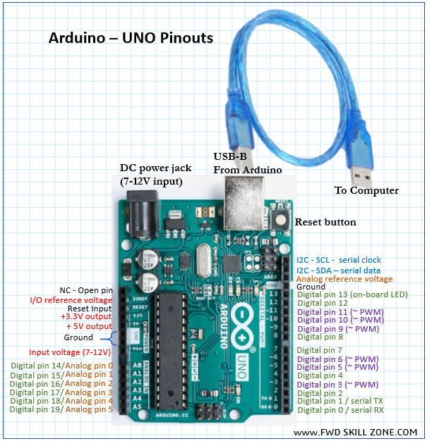
UNO pins - Specialized functions
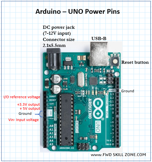
Serial: 0 (RX) and 1 (TX). Used to receive (RX) and transmit (TX) TTL serial data. PWM: 3, 5, 6, 9, 10, and 11. Provide 8-bit PWM output with the analogWrite() function LED: 13. There is a built-in LED driven by digital pin 13. When the pin is HIGH value, the LED is ON, when the pin is LOW, it’s OFF. AREF. Reference voltage for the analog inputs. Used with analogReference() function. Reset. Used to reset the microcontroller. Typically used to add a reset button to shields which block the one on the board Arduino – UNO - Power
The Arduino Uno board can be powered via the USB connection or with an external power supply through the DC power jack. The power source is selected automatically.
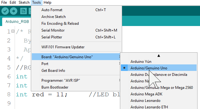
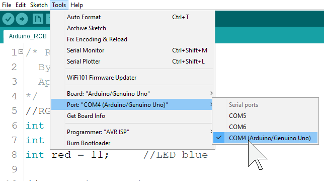
Arduino UNO - SoftwareThe open-source Arduino Software (IDE) makes it easy to write code and upload it to the board. It runs on Windows, Mac OS, and Linux. The environment is written in Java and based on Processing and other open-source software. In order to program the Arduino microcontroller, you need to install the Arduino Desktop IDE ( Integrated Development Environment). The Arduino Software (IDE) allows you to write programs and upload them to your board.
- Install the Arduino IDE from Arduino Software Page. https://www.arduino.cc/en/Main/Software -Scroll down to “Download the Arduino IDE “ -Select the installer according to your computer operating system. Foe example, select “Windows Installer” for Windows7 and up. -Follow the on-screen wizard and finish the installation. Arduino Software (IDE)
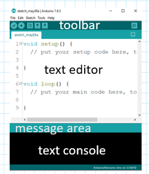
The Arduino IDE - Integrated Development Environment - contains a text editor for writing code, a message area, a text console, a toolbar with buttons for common functions and a series of menus.
Arduino IDE - Toolbar


Verify
Checks your sketch for errors compiling it. Note: Ardunio code is also called “Sketch”. 
Upload
Compiles your code and uploads it to the code to your board configured board. 
New
Creates a new sketch. 
Open
Clicking it will open a Sketchbook it within the current window overwriting its content. If you want to open a file in a folder then use the File | open menu instead. 
Save
Saves your sketch. 
Serial Monitor
Opens the serial monitor that displays a serial message sent from the Arduino board over USB or serial connector Arduino – IDE - Sketch
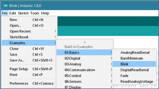
The Arduino Software (IDE) uses the concept of a sketchbook: a standard place to store your programs (or sketches). The sketches in your sketchbook can be opened from the File > Sketchbook menu or from the Open button on the toolbar.The first time you run the Arduino software, it will automatically create a directory for your sketchbook. You can view or change the location of the sketchbook location from with the Preferences dialog. Now, you have the basics of Arduino hardware and software and we are done with the introduction. We are ready to start the hands-on projects Remember, our number one focus is safety and our number one goal is to have fun.
Project 1a. On-board LED Blink
Project 1b. LED BlinkThis project requires Arduino board, LED diode, 200 ohm or equivalent resistor, breadboard (optional), and a USB-B cable.

-Note: the LED’s short leg is cathode (-) and it should be connected to GND (ground). The long leg is anode (+) and it will be connected to a digital pin through a resistor.
Note: if you don’t have a resistor, you can connect the LED directly to the UNO pins but the LED will be more bright. If you do so, please be nice to your eyes!
If you have enjoyed the Arduino beginner tutorial, then check out the intermediate projects under "Arduino 102" section of this website. »»» END of Arduino 101 »»» |
|