Verilog HDL Examples using Xilinx ISE Project NavigatorExample 1.
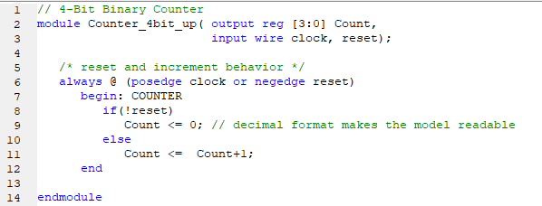
4-Bit Binary Counter The following example demonstrates how we can model a 4-bit binary counter in Verilog. We will use the Verilog "numerical operators" on the "reg" data type such that the counter behavior can be expressed as Counter = Counter + 1 to increment the counting procedure.
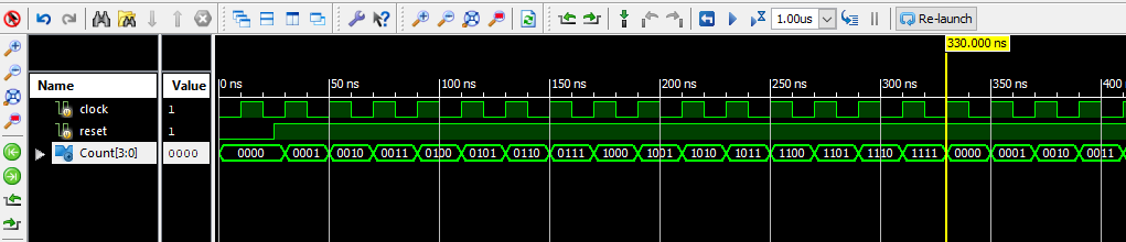
4-Bit Binary Counter Waveform.
Counting from 0000 to 1111.
Example 2.
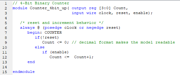
4-Bit Counter with Enable Enable circuit is used to protect the counter from running continuously. When enable is triggered, the counter will increment or decrement on the next positive edge of the clock cycle. When enable is removed, the counter will hold the previous value until the next enable signal is asserted. Example 2 demonstrates how we can model a 4-bit binary counter with enable function.
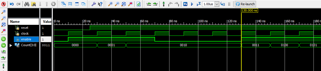
4-Bit Counter with Enable. When enable is removed, the counter will hold the last value.
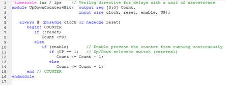
Example 3. 4-Bit Up/Down Counter with Enable and Up/notUp select switch In this example, we will see how to model an up-down counter with an enable function and up/down selector that will set the counter to count either incrementing or decrementing. This example also shows a "timescale" directive that will define the timescale of the delay unit and its smallest precision. A timescale 1ns/1ps declares the unit of time is 1 ns with a precision of 1ps.
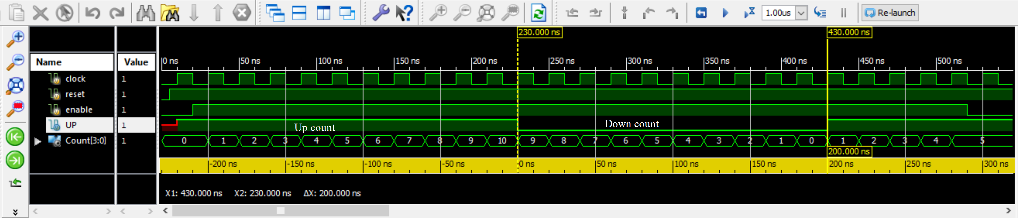
4-Bit Up/Down Counter with Enable and Up/notUp select switch.
Example 4.
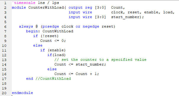
4-Bit Counter with Enable and Load In this example, we will see how to model a counter with an enable function and a load input that will set the counter to a specified value. A counter with a load will set the counter to a specified value from the input port "start_number". The input "start_number" will be loaded to the counter when the "load" signal is asserted and when the clock is its rising edge.
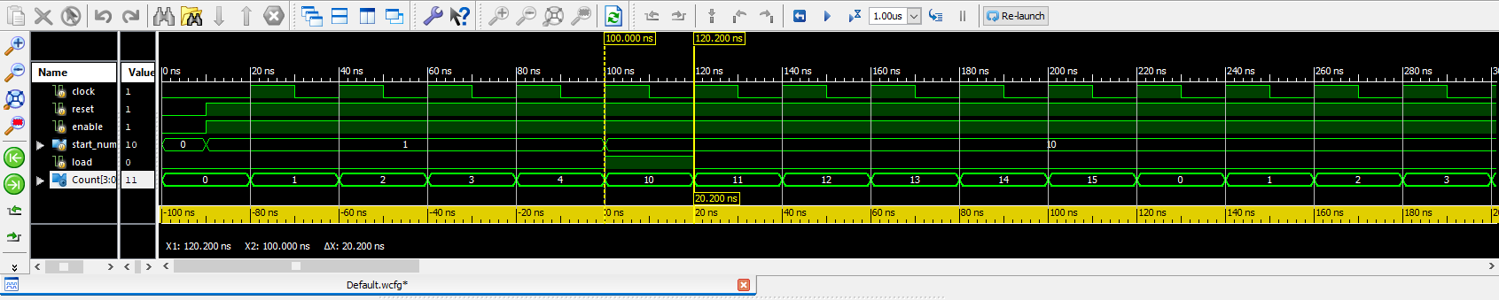
4-Bit Counter with Enable and Load.
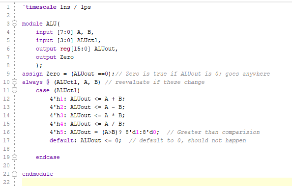
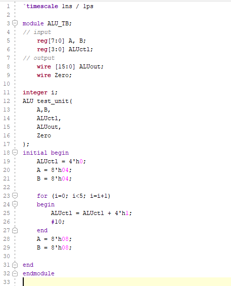
Verilog HDL Examples using Xilinx/AMD VivadoExample 5.
ALU (Arithmetic and Logic Unit) In this example, we will see how to design a Verilog behavioral model of ALU. The module is synthesized using basic libraries containing arithmetic and logical operations.
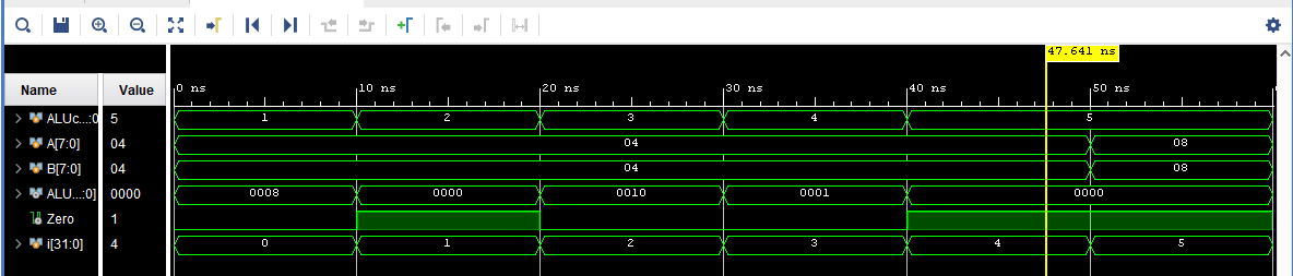
ALU waveform
|